Useful Notes
Toroidal transformers advantages
Technical characteristics
Methods of determining secondary current ratings in D.C. circuits
Toroidal transformers advantages
Advantages of toroidal transformers comparing to conventional transformers
Comparing to conventional transformers the toroidal ones have many advantages that make them very attractive for basic any field in electronics and power engineering:
- High efficiency
- Small size, flexible dimensions
- Low magnetic stray field
- Low mechanical hum
- Low no-load losses
- Low operating temperature
- Good voltage regulation
- Easy to mount
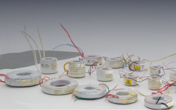
Toroidal transformers applications:
Due to these unique characteristics toroids are now replacing laminated frame types in the most demanding industry applications, like:
- Computers and peripherals
- Telecommunications products
- Industrial controls
- Medical equipment
- Data communications
- Motor controls
- Lighting
- Audio systems
- UPS
- Alarm systems

Technical characteristics
- Mono-phase and three-phase transformers;
- Autotransformers;
- Different dimensions (plate/tall);
- Power: 3-10.000 VA mono-phase, 10-30.000 VA three-phase;
- Primary voltage: 220V; 380V; on request;
- Secondary voltage: up to 5000V;
- Variable number of windings;
- Flash tested: 4kV peak;
- Frequency: up to 400Hz;
- Insulating materials: class E (120C), B (130C), F (150C), H (180C);
- Protection class: IP 00.
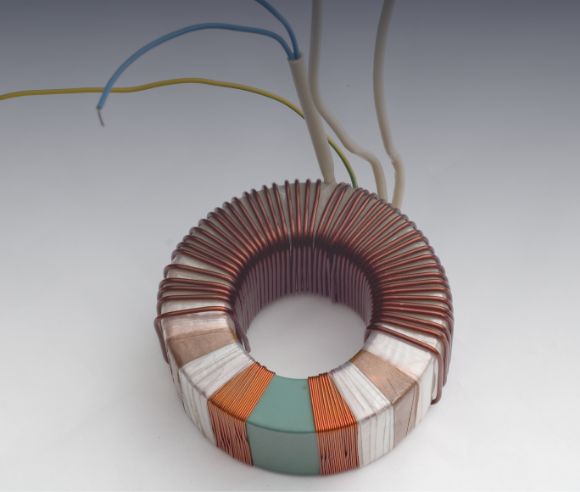
- The magnetic stray field :
The toroidal transformers have a stray magnetic field almost 10 times smaller comparing to laminated transformers. This advantage owes to the construction of the core, which is wound from a continuous ribbon of steel, and to the windings that uniformly encase the core in cooper like a shield, so the magnetic field is held inside the transformer. This way the need for special screening protection can be eliminated, toroidal transformers being suited for sensitive electronic applications like amplifiers, medical equipment, etc.
- Protection against short circuit and overload:
1. Transformers that do not resist the short circuit will be protected using a fuse in the primary circuit. The code of these transformers will contain the letters TH.
2. Transformers that resist at the short circuit and that are protected by incorporated devices will have marked on the label the melting temperature for the thermal fuse and will contain the letters TH in the transformer code.
It is also recommended to protect it by using a fuse in the primary circuit.
- Inrush current:
The excellent magnetic properties of the toroidal transformers can cause a high magnetizing current on turn on. Normally the duration of the inrush current is less than 10 ms and produces no problems in smaller power transformers.
For higher power transformers we recommend the following types of protection:
1. 15 VA – 300 VA – no protection needed.
2. 300 VA – 1 kVA – slow blow fuse.
3. 1 kVA – 2 kVA – small value resistor in series with primary circuit.
4. 2 kVA – 10 kVA – NTC thermistors or start-up circuit like in figure 1.
All our products are made according to customer’s requests.

Methods of determining secondary current ratings in D.C. circuits
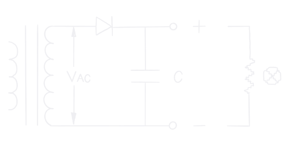
Half Wave Rectifier ( HWR )
- Innefficient, DC flux component;
- Use generally for 0.5 watt or less;
- Without capacitor:
VAC = 2.2 x ( VDC +1 )
IAC = 1.6 x IDC
WATTS = VDC x IDC (output)
VA = 3.5 x ( WATTS + IDC) - With capacitor:
VAC = 0.88 x ( VDC +1 )
IAC = 2.6 x IDC
WATTS = VDC x IDC (output)
VA = 2.3 x ( WATTS + IDC)
Full Wave Center Tap ( FWCT )
- More efficient, although secondary not fully utilized;
- Preffered in very low voltage supplies where extra diode voltage drops unwanted;
- Without capacitor
VAC = 2.2 x ( VDC +1 )
IAC = 0.8 x IDC
WATTS = VDC x IDC (output)
VA = 1.4 x ( WATTS + IDC) - With capacitor
VAC = 1.7 x ( VDC +1 )
IAC =0.8 X IDC
WATTS = VDC x IDC
VVA = 1.4 x ( WATTS + IDC)

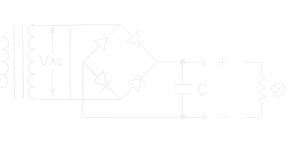
Full wave bridge ( FWB )
- Most efficient, secondary is fully utilized;
- Preffered for smallest transformer size and cost at higher voltages;
- Without capacitor
VAC = 1.1 x ( VDC +2 )
IAC = 1.1 x IDC
WATTS = VDC x IDC (output)
VA = 1.2 x ( WATTS + 2XIDC) - With capacitor
VAC = 0.8 x ( VDC + 2 )
IAC =1.8 X IDC
WATTS = VDC x IDC (output)
VA = 1.4 x ( WATTS + 2XIDC)
Dual complementary rectifies (DCR)
- Most efficient, when load is balanced;
- Provides (+) and (-) with a common ground;
- Without capacitor
VAC = 1.1 x ( VDC +2 )
IAC = 1.1 x IDC
WATTS = VDC x IDC (output)
VA = 1.2 x ( WATTS + 2XIDC) - With capacitor
VAC = 0.8 x ( VDC + 2 )
IAC =1.8 X IDC
WATTS = VDC x IDC (output)
VA = 1.4 x ( WATTS + 2 IDC)

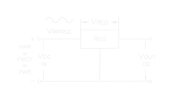
Adding a regulator
VDC= (VOUT + VREG + VRIPPLE ) x VNOMINAL LINE / VLOW LINE ;
Usually VREG >= 3 V, VRIPPLE = 10% x VDC

For orders, questions, details about our products
